Marc Torres 17 Aug 2004
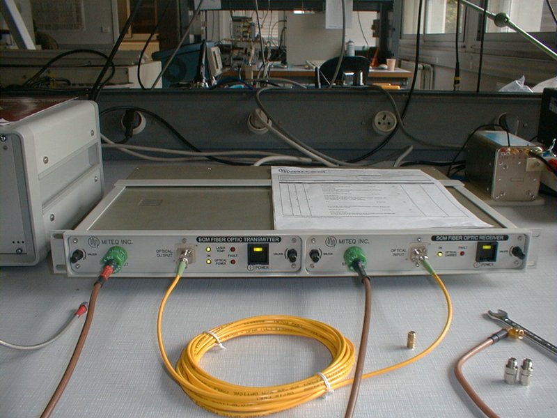
A rack containing both laser and
photoreceiver of the SCM family has been designed by Miteq as a demo
unit. It has been lent to IRAM for evaluating its performance as an IF
signal transport system between antennas and building, in the 4 to 8
GHz range.
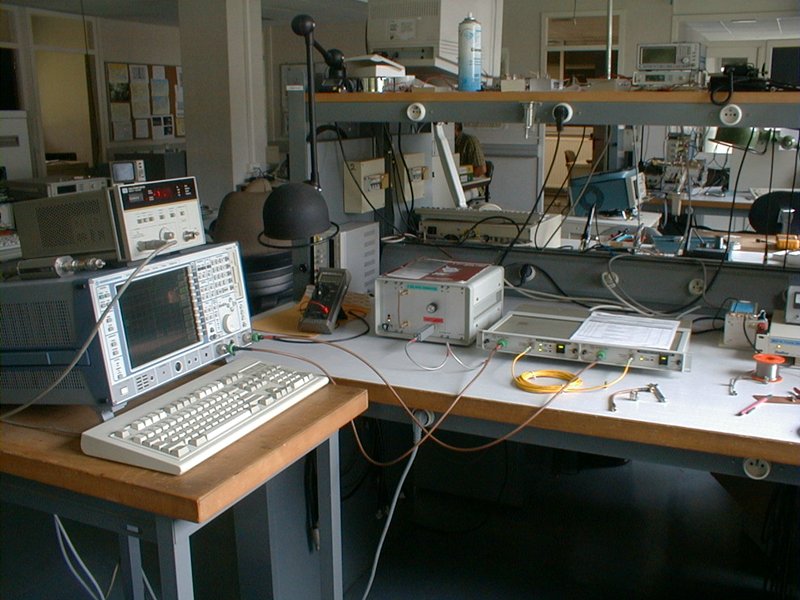
The test setup is on the picture
below. Left of the rack is a home-made noise source, 2 to 4 GHz.
Unfortunately the tracking generator is limited to 7 GHz.
1. Transmission
In the linear region the tested link exhibits a gain of 21-22 dB, in accordance with its individual data sheet.
The product data sheet specifies 14 dB typical.
Measurement is normalized to 0 dB.
2. Dynamic range
Picture below : analyser BW is set to 1 MHz so noise densities can be read directly in dBm/MHz

Red : noise floor of the test setup
Green : photoreceiver noise, dark condition.
Yellow : photoreceiver signal with laser on and no RF applied (laser noise)
Blue : swept RF signal of -45 dBm applied to the transmitter.
3. Non-linearity under White Gaussian Noise
For emulating the IF transport, a 2 to 4 GHz noise band is applied to the transmitter. As its power increases, harmonic distorsion and intermodulation products created by the link produce energy that appears above 4 GHz and below 2 GHz. This energy grows very quickly when the power is raised after some point.
The family of curves below illustrates this effect. They are spaced by 5 dB of input power.
Gain compression begins to be noticed on the yellow one,which is for a total power applied at transmitter of -15.3dBm , to be related to the specified 1dB compression point of -11 dBm. (remember this method of characterization makes use of a single CW signal).
For amplifiers, the rule-of-thumb with Gaussian noise is that they should be operated 15-20 dB below their 1 dB CW compression point.
Lasers seem to behave similarly.
4. Conclusion
The tests described above make use of a bandwidth of exactly one octave (2-4 GHz) , which allows a convenient separation of the unwanted products. For 4-8 GHz the noise densities need to be lowered by 3 dB to keep the total power constant.
For our application we should operate the transmitter at -25 dBm total power maximum (green curve above). This yields a 27 dB "unwanted-noise free dynamic range" .
Assuming a 4 dB fiber loss (mainly connectors), the level recovered at the building can be expected to be close to -7 dBm.