M.Torres Nov 2004
rev Feb 2006
1.
The current situation
There is one analog total power detector on the 1.5 GHz hot IF. It is a coaxial mounted square law diode connected to the IF via a coupler. It is read out by a VME 12-bit ADC register. It is used mainly as a sensor for the receiver tuning software.
The hot IF level can be varied thru a computer-controlled 16 dB attenuator, by 2 dB steps. It is used to compensate for the large variations that occur when the receiver input switches from sky to ambient load.
In the building there are 12 analog total power detectors, of 500 MHz BW, which are read out via a VME 12-bit,16-input multiplexed ADC. There is an hardware integration time constant of 60 ms, and the software provides further integration by averaging 32 measurements every second. Its linearity is undefined. This detector is used while on the sky, to track relative small variations of the level, e.g. caused by clouds, elevation changes...etc. It helps measuring an adequate value of Tsys vs time, across one calibration period, typically 20 minutes.
In autocorrelation mode the correlator units are able to tweak their sampling levels to the optimum V/Sigma but can only deliver relative spectral information on the incoming amplitude. Autocorrelation and cross correlation modes cannot be simultaneous.
2. Changes driven by the new IF system
In the PdBNG receivers, the hot IF total power detector will basically remain the same. A computer-controlled 16 dB attenuator, with 0.5 dB steps will be installed.
The IF will be tranported by optic fiber. The LO reference will continue to travel by the Hi-Q cable
In the building, the analog total power detectors will disappear, because of insufficient BW. The new IF BW is such that both Trec and Tsky are expected to significantly vary across its 4 GHz. These temperatures are wished to be represented as a function of frequency rather than by a single number for the whole band.
3. Proposed solutions
The building total power detectors had two functions:
a) to monitor the transmission across the coaxial cables and connectors
b) to measure the delta power in between the 2 dB steps of the hot IF attenuator and to track small variations of level while observing.
Solution to a)
The optical receivers already include an optical power meter which will be computer-readable. Any abnormal loss in the optic fiber network will be detected.
Solution to b)
Historically the analog detectors have been used mainly because the correlator could not perform auto and cross simultaneously.
During observation, a full auto-spectrum is not really needed, the zero channel (representing the total power) is sufficient to describe the amplitude variations.
It is suggested to retrofit all the 8 units with a "single channel autocorrelator" that can work simultaneously with the cross-correlator while observing.
This would deliver 8 total power channels per antenna, each of them being matched to the actual frequency window that the unit is tuned to. This would allow to feed the atmospheric model with individual "current total power" data, on the places of interest across the 4 GHz IF. If a complete 4 GHz coverage is wanted, two passes will be necessary, because the max possible contiguous BW of the correlator is currently 2.4 GHz.
4. Implementation
For the first phase where the current correlator only will be used, all the existing units will be retrofitted with 6 pairs of "digital power detectors" . The wideband correlator design will include similar ones. Of course their BW will be 2 GHz each (please refer to the IF processor NG overview).
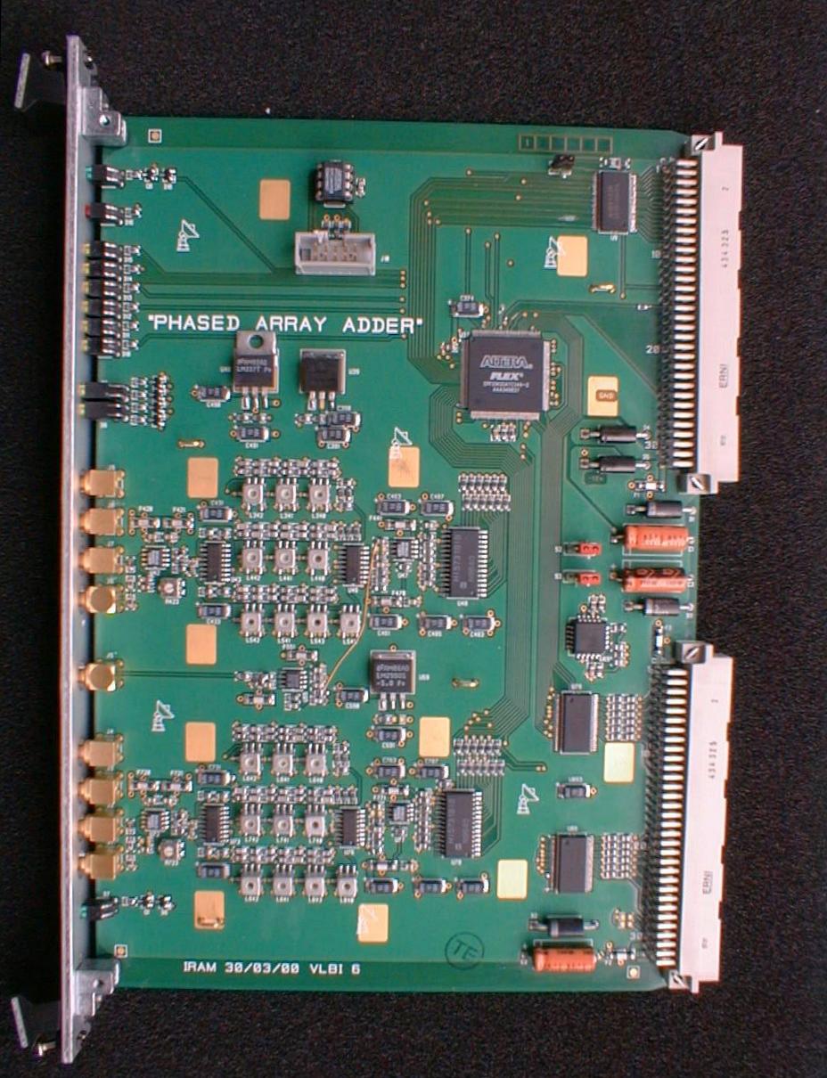
The current correlator units blockdiagram has been updated . The red block represents the retrofitted part. It is located in the VLBI phased array module, where the backplane provides digitized samples emanating from all 6 antennas, both subbands. The samples are decimated, only the 4th samples are present. This does not allow to reach the radiometric noise level, but is largely sufficient for this application. The fluctuation is estimated to be 1/4000 over one second. So the readout needs 12 bits minimum resolution.
The integrated result of the power meter is placed on an 10-bit word every 32Hz interrupt. Readout action will be clearing. The VME computer will further integrate these 10 bits over one second, leading to a 15 bit word representing the "digital total power". Per unit, 12 such words will be delivered every second (6USB and 6LSB, that may be added).
For a traditional analog square law detector, output voltage is proportional to input power. For a digital one, the output is related to the ratio of the RMS input voltage to the decision voltages. The transfer function has the aspect below. Vertical scale is in counts for a 31.25 ms period. Horizontal is in dB with respect to tweak level.
Mesured response curve of a D-TPD
After a "tweak", the samplers operate in the vicinity of
y=356. This is the place where the S/N degradation is minimal,
and where the Van Vleck corrections are designed to operate
properly. Inverting this function can in principle allow
to recover the input power over a large range before truncation errors
start reducing the precision. A range of +/- 5 dB can be reached at 0.2
% error with a simple polynomial.
Installing the new hardware will require to dismount the VLBI phased array modules from their units, to re-program their FPGA's and to practice a moderate amount of surgery on the boards.
Similar operations will be required on the software (TBD).
There is one analog total power detector on the 1.5 GHz hot IF. It is a coaxial mounted square law diode connected to the IF via a coupler. It is read out by a VME 12-bit ADC register. It is used mainly as a sensor for the receiver tuning software.
The hot IF level can be varied thru a computer-controlled 16 dB attenuator, by 2 dB steps. It is used to compensate for the large variations that occur when the receiver input switches from sky to ambient load.
In the building there are 12 analog total power detectors, of 500 MHz BW, which are read out via a VME 12-bit,16-input multiplexed ADC. There is an hardware integration time constant of 60 ms, and the software provides further integration by averaging 32 measurements every second. Its linearity is undefined. This detector is used while on the sky, to track relative small variations of the level, e.g. caused by clouds, elevation changes...etc. It helps measuring an adequate value of Tsys vs time, across one calibration period, typically 20 minutes.
In autocorrelation mode the correlator units are able to tweak their sampling levels to the optimum V/Sigma but can only deliver relative spectral information on the incoming amplitude. Autocorrelation and cross correlation modes cannot be simultaneous.
2. Changes driven by the new IF system
In the PdBNG receivers, the hot IF total power detector will basically remain the same. A computer-controlled 16 dB attenuator, with 0.5 dB steps will be installed.
The IF will be tranported by optic fiber. The LO reference will continue to travel by the Hi-Q cable
In the building, the analog total power detectors will disappear, because of insufficient BW. The new IF BW is such that both Trec and Tsky are expected to significantly vary across its 4 GHz. These temperatures are wished to be represented as a function of frequency rather than by a single number for the whole band.
3. Proposed solutions
The building total power detectors had two functions:
a) to monitor the transmission across the coaxial cables and connectors
b) to measure the delta power in between the 2 dB steps of the hot IF attenuator and to track small variations of level while observing.
Solution to a)
The optical receivers already include an optical power meter which will be computer-readable. Any abnormal loss in the optic fiber network will be detected.
Solution to b)
Historically the analog detectors have been used mainly because the correlator could not perform auto and cross simultaneously.
During observation, a full auto-spectrum is not really needed, the zero channel (representing the total power) is sufficient to describe the amplitude variations.
It is suggested to retrofit all the 8 units with a "single channel autocorrelator" that can work simultaneously with the cross-correlator while observing.
This would deliver 8 total power channels per antenna, each of them being matched to the actual frequency window that the unit is tuned to. This would allow to feed the atmospheric model with individual "current total power" data, on the places of interest across the 4 GHz IF. If a complete 4 GHz coverage is wanted, two passes will be necessary, because the max possible contiguous BW of the correlator is currently 2.4 GHz.
4. Implementation
For the first phase where the current correlator only will be used, all the existing units will be retrofitted with 6 pairs of "digital power detectors" . The wideband correlator design will include similar ones. Of course their BW will be 2 GHz each (please refer to the IF processor NG overview).
The current correlator units blockdiagram has been updated . The red block represents the retrofitted part. It is located in the VLBI phased array module, where the backplane provides digitized samples emanating from all 6 antennas, both subbands. The samples are decimated, only the 4th samples are present. This does not allow to reach the radiometric noise level, but is largely sufficient for this application. The fluctuation is estimated to be 1/4000 over one second. So the readout needs 12 bits minimum resolution.
The integrated result of the power meter is placed on an 10-bit word every 32Hz interrupt. Readout action will be clearing. The VME computer will further integrate these 10 bits over one second, leading to a 15 bit word representing the "digital total power". Per unit, 12 such words will be delivered every second (6USB and 6LSB, that may be added).
For a traditional analog square law detector, output voltage is proportional to input power. For a digital one, the output is related to the ratio of the RMS input voltage to the decision voltages. The transfer function has the aspect below. Vertical scale is in counts for a 31.25 ms period. Horizontal is in dB with respect to tweak level.
Mesured response curve of a D-TPD
Installing the new hardware will require to dismount the VLBI phased array modules from their units, to re-program their FPGA's and to practice a moderate amount of surgery on the boards.
Similar operations will be required on the software (TBD).