This paper is an attempt to summarize several concerns related to the sampler clock module, which IRAM is in charge to built. It is better seen as a design sketch than as an ALMA document.
1/ Disciplining not needed
After several meetings and reviews it has appeared that when all the
demultiplexers involved in one antenna make use of different /16 dividers,
all of them may not have the same phase, and this would result in an impossiblity
for the DTX to catch them all at the same time. To solve this, a technique
called "disciplining" has been proposed and implemented on a test device,
but it has received poor acceptance from the community, probably because
it is expectable that the implementation of this technique on a large scale
would face problems. Since this precludes the use of commercial demultiplexers,
the Bordeaux IC development group has evaluated the possibility of designing
a multibit-demux based on a multichip module (MCM).
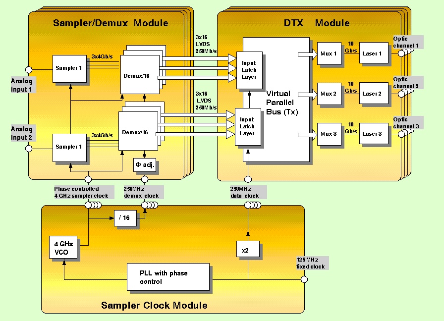
If all the demultiplexers can share a common version of the /16 clock,
the architecture can be greatly simplified, as described by the block diagram
below:
This results in a very straightforward design and a more understandable
system behaviour. One can say it is "functionally correct". The difficulty
of such a scheme is of technical nature and lies in the control of the
timings over a system which is fairly spread in space, and operated at
high speed. Some degree of comfort can be brought by individual phase trimmers,
at the clock distribution level.
2/ Drifting eye pattern
Due to the motion of the source in the sky, the demux 250 MHz clock
is drifting compared to the DTX clock, and some impossibility of catching
stable data at the DTX input layer will result, from time to time. This
problem has been exposed (M. Torres,"Demux
considerations" Granada Apr.2002) and a solution called "clock rewinding"
was proposed to solve it. The idea is that when the timing drifts too much,
the clock is softly rewinded by one turn, and the data is simultaneously
shifted by one bit in the digital delay line. This is basically what we
do twice a year at 2.00 am with daylight saving time. The clock design
described here makes allowance for its implementation, if found necessary.
3 / Sampler clock module functional architecture
The system requirements defined above can be fulfilled by the engineering solution proposed below:
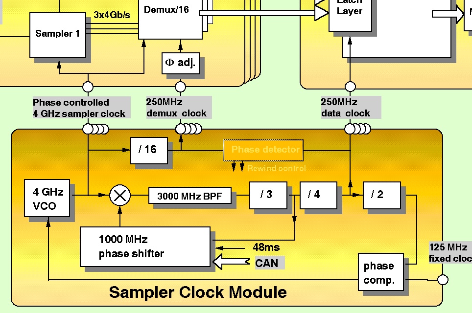
The controlled phase shift is applied at 1000 MHz, where many devices are commercially available with the required accuracy. It will be transferred to the 4GHz VCO with no multiplication, since the /24 divider chain imposes a fixed-phase 3GHz frequency. Fixed- phase 250 MHz for the DTX and 1000 MHz for the shifter are tapped along the dividing chain.
The 4 GHz sampler clock is distributed to the sampler modules as a sinewave
via a 4-way splitter.
A /16 divider provides the unique version of the demux clock, which
is also distributed as a sinewave thru a 4-way splitter.
The fixed 250 MHz to DTX interface is electrically TBD, and the number
of copies to deliver, if any.