Astron. & Astrophys. Suppl. 133, 271 (1998)
A. Greve ![]() , C. Kramer
, C. Kramer ![]() , W. Wild
, W. Wild ![]()
![]() IRAM, 300 rue de la piscine, F-38406 St Martin d'Hères, France
IRAM, 300 rue de la piscine, F-38406 St Martin d'Hères, France
![]() IRAM, Nucleo Central, Avda. Divina Pastora 7, E-18102 Granada, Spain
IRAM, Nucleo Central, Avda. Divina Pastora 7, E-18102 Granada, Spain
![]() I. Physikalishes Institut, Universität zu Köln, Zülpicher
Strasse 77, D-50937 Köln, Germany
I. Physikalishes Institut, Universität zu Köln, Zülpicher
Strasse 77, D-50937 Köln, Germany
Astron. & Astrophys. Suppl. 133, 271 (1998)
Wavel./Freq. ![]()
![]()
![]()
![]()
![]()
B ![]()
F ![]()
![]()
![]()
S/T ![]()
![]()
P ![]() (
( ![]()
![]() )
)
P ![]() (
( ![]()
![]() )
) P ![]() (
( ![]()
![]() )
)
[mm]/[GHz] [''] [''] [ ![]() ]
] [ ![]() ]
] [ ![]() ]
] [ ![]() ]
] [Jy/K]
[ ![]() ]('')
]('') [ ![]() ]('')
]('') [ ![]() ]('')
]('') 3.4 / 88 27.5 ![]() 64
64 61 ![]() 3
3 73 ![]() 3
3 92 ![]() 2
2
94 ![]() 4
4 5.9 ![]() 00.3
00.3 3 ![]() 1(300)
1(300) 3(410) 20(2500)
2.0 / 150 16.0 ![]() 38
38 45 ![]() 3
3 54 ![]() 3
3 90 ![]() 2
2
92 ![]() 4
4 7.8 ![]() 0.5
0.5 7 ![]() 3(175)
3(175) 8(280) 25(1500)
1.3 / 230 10.5 ![]() 25
25 35 ![]() 3
3 42 ![]() 3
3 86 ![]() 2
2
85 ![]() 4
4 9.7 ![]() 0.9
0.9 15 ![]() 5(125)
5(125) 12(180) 26 (950)
[0.86 / 350 8.5 ![]() 20
20 16 ![]() 4
4 19 ![]() 4
4 75 ![]() 3
3
22 ![]() 3
3 20 ![]() 5 (85)
5 (85) 20(160) 30(580)] ![]()
Update from the values compiled by Kramer (1997).
The entries of the Table are:
![]()
![]() : beam width (FWHP) (measured);
: beam width (FWHP) (measured); ![]()
![]() : full
width (to first minimum),
: full
width (to first minimum), ![]()
![]()
![]() 2.4
2.4 ![]()
![]() (calculated);
(calculated);
![]() : aperture efficiency (measured
: aperture efficiency (measured ![]() calculated from
calculated from
![]()
![]() );
B
);
B ![]() : main beam efficiency, B
: main beam efficiency, B ![]()
![]() 1.20
1.20 ![]() ;
;
F ![]() : forward efficiency (from sky dips),
: forward efficiency (from sky dips), ![]()
![]() : Moon
efficiency (measured);
: Moon
efficiency (measured);
S/T ![]() = (2k/A)F
= (2k/A)F ![]() /
/ ![]() =
3.906F
=
3.906F ![]() /
/ ![]() : antenna gain (calculated
: antenna gain (calculated ![]() measured).
measured).
P ![]() - P
- P ![]() : relative power of the error beams (calculated). The
accuracy of the values is
: relative power of the error beams (calculated). The
accuracy of the values is ![]()
![]() 5
5 ![]() . The entries of P
. The entries of P ![]()
illustrate the partially transient nature of this error beam. In brackets are
given the widths (FWHP) of the
corresponding error beams.
* not frequently used frequency and somewhat poorly known telescope
performance. *
The values valid before July 1997 are published by Kramer (1997) and are
found in the 30-m Telescope Manual (Wild).
Total power scans across the Moon around New Moon (mostly day time) and Full
Moon (night time) at 3.4 mm (88 GHz), 2.0 mm (150 GHz), 1.3 mm (230
GHz), and 0.86 mm (350 GHz) wavelength are used to derive the beam pattern of
the IRAM 30-m telescope to a level of approximately -30 dB (0.1
![]() ) and, dependent on wavelength, to a full width of 1000 - 1400''. From
the reflector surface construction and application of the antenna tolerance
theory we find that the measurable beam consists of the diffracted beam, two
underlying error beams which can be explained from the panel dimensions, and a
beam deformation mostly due to large-scale transient residual thermal
deformations of the telescope structure. In view of the multiple beam structure
of the 30-m telescope, and of other telescopes with a similar reflector
construction of (mini-)panels and panel frames, we summarize the
antenna tolerance theory for the influence of several independent
surface/wavefront deformations. This theory makes use of different correlation
lengths, which in essence determine the independent error distributions, and
of the wavelength-scaling of the diffracted beam and of the error beams.
) and, dependent on wavelength, to a full width of 1000 - 1400''. From
the reflector surface construction and application of the antenna tolerance
theory we find that the measurable beam consists of the diffracted beam, two
underlying error beams which can be explained from the panel dimensions, and a
beam deformation mostly due to large-scale transient residual thermal
deformations of the telescope structure. In view of the multiple beam structure
of the 30-m telescope, and of other telescopes with a similar reflector
construction of (mini-)panels and panel frames, we summarize the
antenna tolerance theory for the influence of several independent
surface/wavefront deformations. This theory makes use of different correlation
lengths, which in essence determine the independent error distributions, and
of the wavelength-scaling of the diffracted beam and of the error beams.

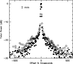
Figure: Composite profiles f ![]() (u) which illustrate the improvement
of the reflector surface accuracy; measurements before July1997 (24 Dec 1994):
open circles, after July 1997 (19 Nov 1997): solid dots.
(u) which illustrate the improvement
of the reflector surface accuracy; measurements before July1997 (24 Dec 1994):
open circles, after July 1997 (19 Nov 1997): solid dots.
From the Moon scans we derive the parameters for calculation of the 30-m
telescope beam in the wavelength range 3 mm to 0.8 mm as required for the
reduction of astronomical observations, in particular of extended sources.
The parameters of the beam are primarily for the time after July 1997 when
the reflector was re-adjusted and improved to the illumination weighted
surface precision of ![]()
![]() = 0.065 - 0.075 mm.
= 0.065 - 0.075 mm.

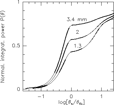
Figure: Relative power P( ![]() ) (Eq.(24)) received in the solid angle
) (Eq.(24)) received in the solid angle
![]() of opening
of opening ![]()
![]() given in fractions of the full beam
width
given in fractions of the full beam
width ![]()
![]() (Table 2). P(
(Table 2). P( ![]() ) at
) at
![]()
![]() /
/ ![]()
![]() = 1 is the beam efficiency
B
= 1 is the beam efficiency
B ![]() ; the normalization of the curves is made to these values given in
Table 1. The values are shown for
; the normalization of the curves is made to these values given in
Table 1. The values are shown for ![]()
![]()
![]() 1000 -
1400'', i.e. the extent of the profile measurements where also F
1000 -
1400'', i.e. the extent of the profile measurements where also F ![]()
![]()
![]()
![]() (Table 1). The remaining energy for larger
angles
(Table 1). The remaining energy for larger
angles ![]()
![]() is mainly in the backward beam and is of the order
1 - F
is mainly in the backward beam and is of the order
1 - F ![]() .
.