![]()
M.Torres, J.Y.Mayvial, March,2001
![]()
M.Torres, J.Y.Mayvial, March,2001
1.Introduction
The digitizer modules will require a 4GHz clock, with variable phase
so as to compensate for the fractional part of the geometrical delay. The
other methods of compensation, such as linear weighting of the FFT input,
or the introduction of complex coefficients in the FIR filter, are estimated
heavier to implement. The solution of shifting the sampler clock is quite
easy to achieve, but has the disadvantage of transferring some
difficulty at the system level, where moving eye diagrams are to
be dealt with.
For convenience, the clock generator will provide 8 independent outputs.
The rate of change of the fractional delay value is handled by the module
itself, so the software does not need to write it too frequently.
2.Discussion
Basically there are two ways of solving this problem:
The analog way makes use of analog phase shifters, that can
be of the varactor-loaded hybrid or of the I-Q type. Both need to be PROM-compensated
in order to reach the desired linearity.
The digital way makes use of a DDS chip who generates a fully-steerable
sinewave at a low frequency, and a PLL to translate this low frequency
up to the required value.
The experience acquired on various generations of correlators on the
Plateau de Bure has shown that the digital implementation is much more
reliable and insensitive to aging. The additional complexity of this solution
is now largely absorbed by the recent DDS commercial chips.
3. Description
The module elaborates a 3984.375 MHz frequency from the reference signals
and distributes it to 8 adding PLL's which each receive a 15.625 MHz phase-controlled
signal delivered by a DDS chip. The net result is a 4.000GHz output sinewave
that can be phase/frequency controlled around this center value.
Fig.1 Block diagram of the clock generator
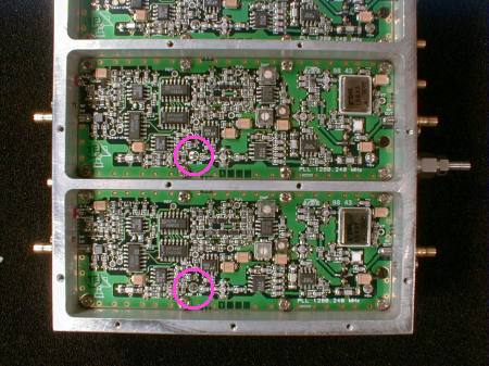
The performance of such a subsystem largely depends on its physical layout. The 8 VCOs operate at the same frequency and need to be drastically isolated from each other, for both conducted and radiated coupling. A proven way to achieve this isolation is to built a special double-deck housing, with the lower deck subdivided in 8 independent enclosures.
A similar assembly has already been built for the Plateau de Bure interferometer, with 6 PLLs operating at the frequency of 1280 MHz. The interaction between outputs has been measured less than a few tenths of a degree.
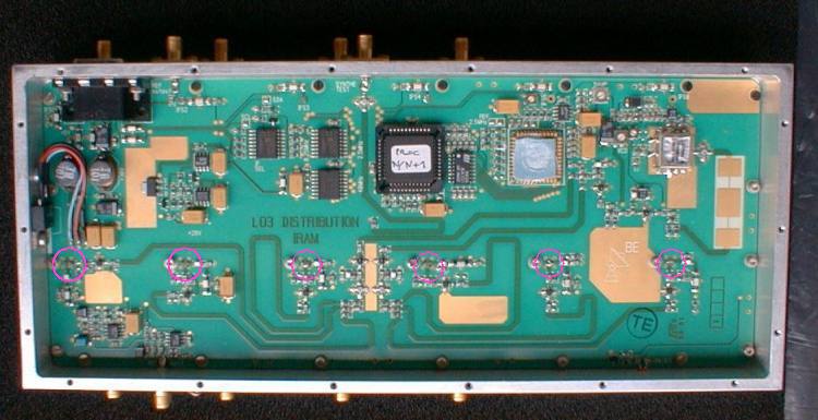
Picture 1: View of the upper deck, main frequency synthesizer.
Both pictures: The pink circles show the matched connections to the lower deck.