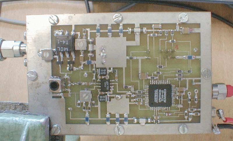
Figure 1. Top view of the circuits.
José
A. López-Pérez, Marc Torres.
IRAM,
1999.
Abstract
This report describes the measurements of a retrofitted commercial comb generator to obtain a 1MHz Phase Calibration signal for VLBI.
With a time domain filtering technique previously
used at Haystack Observatory and a low cost card, we have transformed a
20 MHz commercial comb generator into a 1 MHz one, whose frequency range
spans from 100 MHz to 1200 MHz with a reasonable output power and a very
good phase stability.
Theory of operation
In time domain, the output of the 20 MHz commercial comb generator is a periodic signal consisting of narrow impulses (rise time < 300 ps) every 50 ns. In frequency domain, this is a set of lines with a 20 MHz step.
Basically, what we have done is to install a SPDT GaAs switch at the output of the commercial comb that sends 1 impulse to the output and 19 impulses to a 50W load. This new output will be a periodic signal with the same kind of impulses but every 1 ms in time domain and a train of lines with 1 MHz step in frequency domain. It also can be seen as if we open a time window to catch one impulse every twenty impulses.
It is very important not to disturb the shape of
the pulse because of its high spectral content and to have a good synchronization
between the window and the signal to be filtered.
The circuits
The commercial comb generator is a MITEQ CMB-103936 and the switch is a Mini-Circuits KSWA-2-46 whose control signals are the complementary outputs of an ALTERA EMP7064STC44-10 Programmable Logic Device (PLD) configured as a divider by 20. Finally, there is a circuit that is able to shift the 20 MHz clock of the Altera for timing synchronization and a doubler at the input of the whole circuit because we have fixed a 10 MHz input signal. This doubler feeds the commercial comb generator and a small fraction of its output is taken by the timing circuit to provide a clock for the PLD. All this circuits can be seen in the picture below.
Figure 1. Top view of the circuits.
The measurements
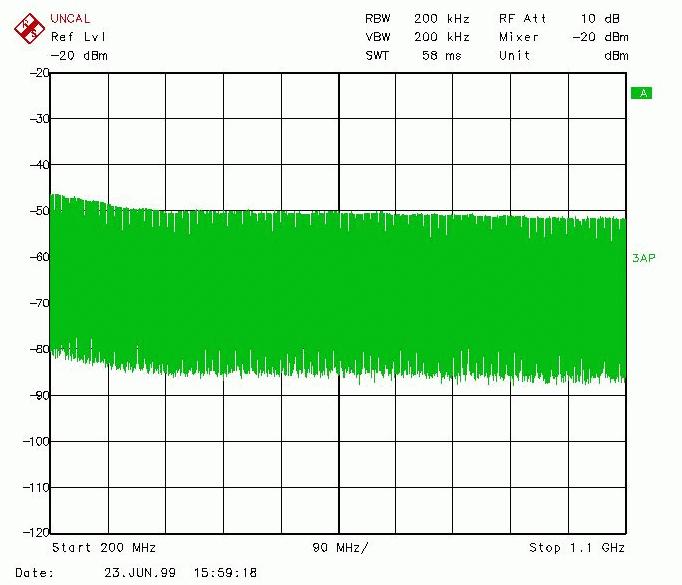
The output of the comb generator over the whole bandwidth of interest is shown in figure 2. We can see a good flatness over the band and the output power is -50dBm for each line.
A zoom of figure 2 around 800 MHz is given in figure 3, where we can see the lines at 1 MHz steps.
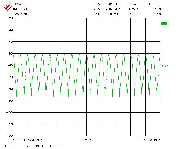
Figure 3. Some lines around 800 MHz.
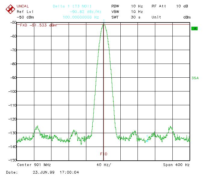
Finally, we present in figure 4 a fine measurement of the shape of one line. We can observe that the phase noise is very low (-90dBc/Hz at 100 Hz).
The long term phase stability has been checked by
phase comparing one line around 1 GHz and a synthesiser locked to the same
frequency. Reasonable mechanical and thermal stress was applied and did
not affect the phase by more than 5 degrees.