Anritsu MG3692B


The generator under test is CW only  (modulation options deleted) and the 0-2GHz option is deleted as well. For this reason the usual phase meter setup could not be used.
But since I had two generators I could set them at a higher frequency (around 8.5 GHz) and phase-compare them in an  mixer. One can assume that if the two generators are of the same quality, the phase noise of every one is smaller by one square root of two than the measured result.

The rotary button can be assigned to phase control with one degree steps that are fairly accurate. This is used to drive the mixer operating point close to DC, and to calibrate the display.

This instrument has a new feature that allows to select 4 loop bandwidths for its internal 10 MHz PLL, the one which locks the internal Xtal to the external 10 MHz source. This is interesting because the high quality signal delivered by the Maser is generally corrupted at this point. See effect on spectrum

The 10 MHz amplitude is set at +10 dBm.
The best phase noise performance is obtained for the highest loop BW (300Hz), as one should expect (fig.1).


Fig.1 Phase noise @ 8.5 GHz with four calibration steps at left

The gain of the mixer is calibrated by stepping the generator phase by 1 degree at the beginning of the record.

If the loop BW is reduced to 10 Hz, faster artifacts from the internal Xtal do show up (fig.2) but slow components stay similar.


Fig.2 same conditions as fig.1, but with reduced loop BW


This instrument, like many others, is sensitive to the amplitude of the external 10 MHz  delivered. If the amplitude is lowered to 0 dBm, the noise increases significantly. (See fig.3, which directly compares to fig.1)


Fig.3 same as fig.1, but with reduced 10 MHz amplitude


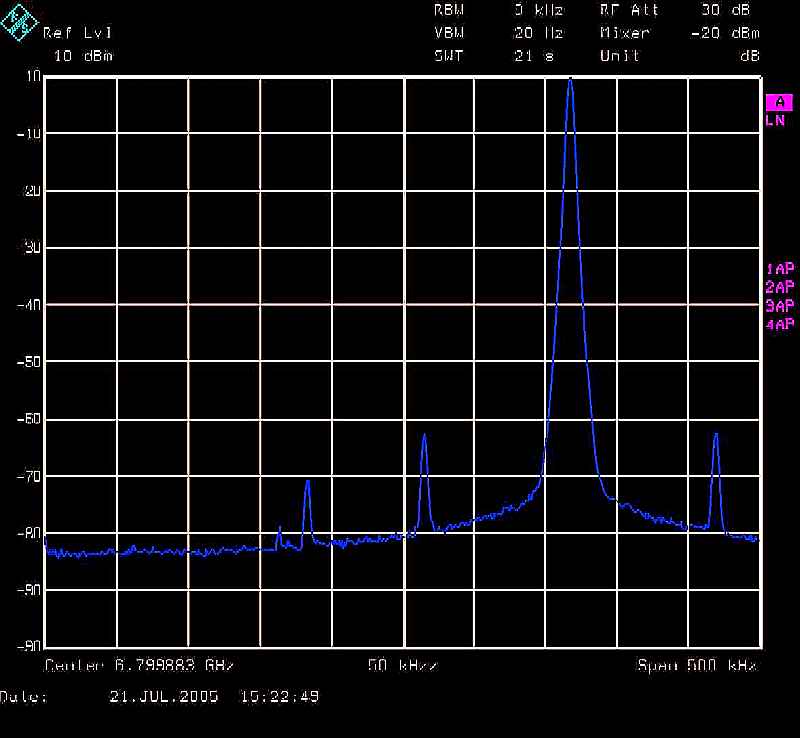
A few spurious lines are present, all within specification <60 dBc. See below.


Fig.4  Big line at 102 kHz offset.


The phase noise is good, with -113dBc/Hz @ 5kHz offset, at 6.8 GHz. Curiously, in the ~500Hz offset range, it is better when running on the internal crystal than on the external. Fig.5 shows when in lock (green) and with 10 MHz BNC removed (red).That means  that the 10 MHz PLL adds phase noise in that range. Probably a lower integrated PN could be obtained by substituting the external 10 MHz to the internal, if this is feasible.


Fig. 5  Ext 10 MHz (green) vs. int (red)


Back to synthesizer test main page