Coupling Optics
Up to and including the antenna, the astronomical signal propagates in free space. On the other hand, the first signal processing unit, the mixer, requires the electromagnetic energy to be confined by metallic walls, in a waveguide. The transition between these two modes of propagation occurs at the horn.

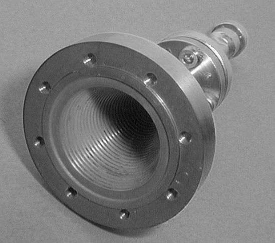
A corrugated horn for the 150GHz band. The phase-correcting lens normally present at the aperture has been removed to reveal the corrugations. The diameter of the aperture is about that of a typical coin (1DM/100Ptas/1F). All the waves collected by the 30-m antenna converge to the horn with a precise phase relationship and are then squeezed into a waveguide 2 x 1mm across.
Assume for a moment that the horn would be placed at the Cassegrain focus of the antenna. Good matching would be difficult to achieve because the field amplitude from a point source (Airy pattern) exhibits radial oscillations alternating between positive and negative values, and has a scalesize proportional to wavelength. These problems are avoided by coupling, via suitable relay optics, the horn to an image of the aperture. This fulfills the condition of frequency-independent illumination. In other words, imagine that we propagate the horn mode back to the antenna aperture as if we were dealing with a transmitter, then the illumination pattern is independent of frequency. Using suitably designed corrugations on the inner wall of the horn the TE10 mode of the rectangular waveguide couples to a mode at the aperture of the horn whose amplitude has circular symmetry, and whose polarization is pure linear.