Photon-assisted tunneling
All mixers in IRAM receivers are based on SIS junctions. An SIS junction consists
of two layers of superconducting metal (Niobium) separated by a few nanometers
of insulator (Aluminum oxide). The insulator is so thin that charged particles
can tunnel through the barrier. The area of a junction is typically one to a
few ![]() . SIS junctions
operate at the boiling temperature of He: 4.2K (at sea level).
. SIS junctions
operate at the boiling temperature of He: 4.2K (at sea level).
Two kinds of charged particles can exist in a superconductor:
a) ordinary electrons;
b) so-called Cooper pairs, consisting of two electrons interacting and weakly bound together by the exchange of phonons (lattice vibrations);
breaking a Cooper pair costs an energy ![]() .
Correspondingly, two kinds of currents can flow across the junction:
the Josephson current, consisting of Cooper pairs, and the so-called quasi-particle
current, consisting of ``ordinary'' electrons (presumably ``electron'' did not
sound fancy enough). To keep this digression into SIS physics short, let's just
state that the Josephson current can be ignored. At the operating temperature
of the mixer, and in an unbiased junction, the population of quasi-particles
is virtually negligible. But, if the bias voltage is raised to the gap voltage
.
Correspondingly, two kinds of currents can flow across the junction:
the Josephson current, consisting of Cooper pairs, and the so-called quasi-particle
current, consisting of ``ordinary'' electrons (presumably ``electron'' did not
sound fancy enough). To keep this digression into SIS physics short, let's just
state that the Josephson current can be ignored. At the operating temperature
of the mixer, and in an unbiased junction, the population of quasi-particles
is virtually negligible. But, if the bias voltage is raised to the gap voltage
![]()
the flow of quasi-particles across the junction becomes possible because the energy gained across the drop of electrical potential compensates for the energy spent in breaking a Cooper pair. See on the following figure the ``LO off'' I-V characteristic.
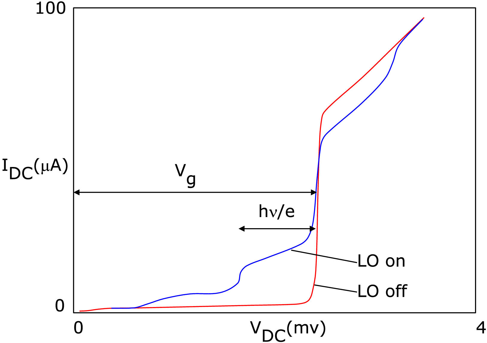
Current-voltage characteristics of an SIS junction operating in a mixer. The two curves were measured without and with LO power applied (frequency 230GHz); they have been slightly idealized (for pedagogical reasons, of course).
In the presence of electromagnetic radiation, the situation is modified as
follows. If a RF photon is absorbed, its energy ![]() can contribute to the energetic budget, which can now be written as:
can contribute to the energetic budget, which can now be written as:
![]()
or, equivalently:
![]()
In other words, the onset of conduction occurs at ![]() .
The region of the I-V curve below the gap voltage where photon-assited tunneling
occurs is called the photon step. See the ``LO on'' curve on the above
figure. The figure is based on actual measurements of a 2-junction series array:
the voltage scale has been scaled 1/2 to illustrate a single junction. For a
more detailed analysis of SIS junctions and their interaction with radiation,
see K.Schuster' s introduction to SIS junctions, or Gundlach 1989 (NATO ASI
series, F59, p259). So far I' ve shown you qualitatively that an SIS junction
can function as a total power detector. The responsivity (current generated
per power absorbed) can even be estimated to be of the order of one electron
per photon, or:
.
The region of the I-V curve below the gap voltage where photon-assited tunneling
occurs is called the photon step. See the ``LO on'' curve on the above
figure. The figure is based on actual measurements of a 2-junction series array:
the voltage scale has been scaled 1/2 to illustrate a single junction. For a
more detailed analysis of SIS junctions and their interaction with radiation,
see K.Schuster' s introduction to SIS junctions, or Gundlach 1989 (NATO ASI
series, F59, p259). So far I' ve shown you qualitatively that an SIS junction
can function as a total power detector. The responsivity (current generated
per power absorbed) can even be estimated to be of the order of one electron
per photon, or: ![]() . How does that
relate to frequency downconversion ? Assume that a power detector is fed the
sum of a local oscillator (normalized to unit amplitude for convenience)
. How does that
relate to frequency downconversion ? Assume that a power detector is fed the
sum of a local oscillator (normalized to unit amplitude for convenience) ![]() and a much smaller signal at a nearby frequency:
and a much smaller signal at a nearby frequency: ![]() .
Assumes this functions as a squaring device and discard high-frequency terms
in the output:
.
Assumes this functions as a squaring device and discard high-frequency terms
in the output:
![]()
So, a power detector can also function as a frequency downconverter (subject
to possible limitations in the response time of the output). The LO power requirement
for an SIS mixer can be estimated as follows. A voltage scale is defined by
the width of the photon step: ![]() .
Likewise, a resistance scale can be defined from RN,
the resistance of the junction above Vg; junctions
used in mixers have
.
Likewise, a resistance scale can be defined from RN,
the resistance of the junction above Vg; junctions
used in mixers have ![]() . So, the
order of magnitude of the LO power required is:
. So, the
order of magnitude of the LO power required is:
![]()
about 20 nW for a 230 GHz mixer. This makes it possible to use the wasteful
coupler injection scheme discussed above. Because the insulating barrier of
the junction is so thin, it posesses a capacitance of about ![]() .
At the RF and LO frequencies, the (imaginary) admittance of that capacitance
is about 3-4 times the (approximately real) admittance of the SIS junction itself.
Therefore, appropriate tuning structures must be implemented to achieve a good
impedance match (i.e. energy coupling) of the junction to the signals. The minimum
theoretical SSB noise for an SIS mixer is
.
At the RF and LO frequencies, the (imaginary) admittance of that capacitance
is about 3-4 times the (approximately real) admittance of the SIS junction itself.
Therefore, appropriate tuning structures must be implemented to achieve a good
impedance match (i.e. energy coupling) of the junction to the signals. The minimum
theoretical SSB noise for an SIS mixer is ![]() ,
11K at 230GHz; the best IRAM mixers come within a factor of a few (4 times)
of that fundamental limit. These numbers are for laboratory measurements with
minimal optics losses; practical receivers have a slightly higher noise.
,
11K at 230GHz; the best IRAM mixers come within a factor of a few (4 times)
of that fundamental limit. These numbers are for laboratory measurements with
minimal optics losses; practical receivers have a slightly higher noise.
![]()
![]()