Optimal amplitude setting across the signal chain
M.Torres, Feb 2012
The S/N performance of a radiotelescope is set by its antenna and receiver - provided that nothing degrades it later- .
Before the astronomical signal can reach the computer, it has to transit through many devices, each of them creating a small amount of unwanted energy, largely depending on its operating level.
If too low, the thermal noise floor may add significantly to the signal. If too high, the circuits produce distorsion, which can be regarded as an additional noise input. In the digital process, amplitude effects are encountered with different names, but they are basically similar.
1.Optic transmission.
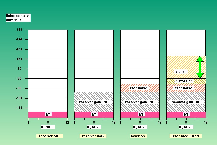
1/ Modulation depth
The laser module can be though of as an ancient AM transmitter, its carrier wavelength being nanometers instead of meters. With unmodulated carrier, the transmission link has some noise floor. When modulation is applied, the detected signal raises above it, depending on the modulation index, desirably as high as possible. At some point the distorsion overcomes the improvement in S/N. This is the best operating point. It has to be servoed by a software ALC loop, that activates whenever the receiver power output is suspected to change significantly.
2/ Optical losses
The optic fiber length causes losses, but actually much less than weared connectors, poor splices or excessive bending. For every station, the optical loss of the trip can be estimated by monitoring the built-in light level meters at both sides. A 3dB optical loss (light power divide by 2) causes a 6 dB (detected voltage divide by 2) loss in IF transmission. An optical loss does not affect the transmission S/N (as long as the laser noise dominates), but it quickly affects the operating level of the following electronics.3/ Flatness
It is desirable that the fiber loss does not change too much with stations . Optical attenuators can be inserted to standardize the network to a reasonable value, e.g. 3dB.
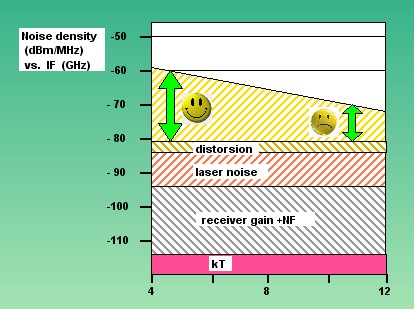
The hot IF output (4-12 GHz) is generally not flat. The weakest portions of the spectrum will have less headroom above the noise floor, and will suffer S/N degradation. The signal density needs to be superior by 20 dB in order to get less than 1% degradation in global Tsys. Further equalization may restore flatness, but degradation is irreversible. The best possible equalization needs to be performed before entering the laser modulator.
2.IF processor
1/ 2nd conversion
The splitting of the IF gives a 3dB advantage regarding dynamic range. The processing is quite simple, and "there is plenty of room below" and above as well. No adjustment is necessary, the unavoidable level variations caused by the IF transport are integrally transmitted to the correlator.2/ Noise source switch
The noise source delivers a fixed, nominal level to the correlator. When switched to signal, the IF processor can deliver +6dB to -10dB from nominal level to the correlator with negligible degradation.3.Correlator
The 0-4GHz baseband entering the ADC might be not flat in frequency . In spite of excellent IF engineering, more than 3 dB across are common. This causes the relative importance of quantization error to increase at the places where the signal density happens to be low. The exact degradation is quite difficult to evaluate for a digital hybrid machine ( PFB+FFT) but simple practice may avoid further degradation as the signal penetrates through the layers of the process.
1/ Main ALC loop Before entering the ADC, the histogram of the input gaussian signal (in time domain) is set to some optimal value by means of a variable gain amplifier (VGA). The purpose of this operation (called "tweak" in Iram jargon, Automatic Level Control loop for the correct engineer) is to occupy all the levels of the digitizer in the best possible way. It results in an optimal "digital RMS" value for the global digital stream. Should the input power change, the gain has to be changed to keep it constant. The correcting range of the VGA is +6...-10dB from nominal level. This correction is not very frequent, several minutes are typical. 2/ Digital equalizer loop The polyphase filterbank divides the digital stream into 64 streams, each representing a primary channel of the input spectrum. If the input is not flat, the 64 digital RMS values for the streams will be unequal. At this point it is worth to make them equal before entering the FFT engines, so all of them are operated at their optimal level. A convenient place to implement this function is the digital complex multiplier, whose argument is used for the L03 fringe rotator. Its module is used as a digital gain element to compensate a +/- 6dB range (a linear 0.5 to 2.0 coefficient). More detail on loop sequences | 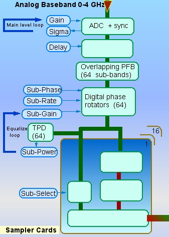 |
Conclusion
Three ALC loops are necessary for the signal chain to operate properly.
The weakness of an element cannot be compensated by applying a correction to another one. Global efficiency requires that each element is operated at its optimum level.