

The `receiver' includes the cryostat (windows, horn, mixer,...) and some optics (LO injection system, dichroic diplexer allowing to separate rays of different wavelengths, polarisation grids,..). The telescope also consists of optical parts (primary and secondary mirrors, Nasmyth mirrors). In the following, we will include in the `receiver' all the optics between the cryostat and a `standard reference plane' located just outside the first polarization grid (i.e. located between this grid and the telescope vertex) and `telescope' all the optics beyond this plane. Receiver temperatures are normally measured by holding HOT/COLD loads in this plane.
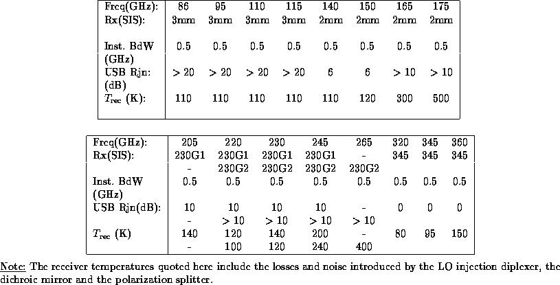
As of today (Oct 1994) the receiver characteristics shown in Table 2 apply (or are expected for next winter).
Table: Receiver characteristics
The above receiver temperatures are relative to the `standard reference plane',
just outside the first polarisation splitter. They include the cross
polarisation losses, as well as the ohmic and spillover losses between the receiver
window and this plane, but assume that the `dichroic mirror' (which allows the
simultaneous operation of 3 receivers) is optimized for this particular
receiver. It is possible to optimize correctly the 3mm and 230G1 receivers
simultaneously when their operating frequencies are the double (or the triple)
of each other. The usual rule is then to optimize 230G1 (which is more
critical). The losses in the dichroic diplexer are then  ; their
contribution is already included in the
  above. If both frequencies are
not exact multiples, typically 5-10 K (an extra
  ) should then
be added to the
  of the 3mm receiver.
When the frequencies of the 3mm and 230G1 receivers are neither double or triple of each
other, high losses ( ) may occur. When optimizing 230G1, the 3mm receiver
temperature can be increased (for some unfavorable cases,
like 90/230 GHz) by 30-40 K (
 =0.1-0.13). When optimizing the 3mm
receiver,
  of 230G1 can be increased by more than 200 K and this receiver may become practically
useless. The reader is referred to IRAM internal report [1] for details.
Note that the receiver temperatures calculated by `OBS' and plotted on the
`RED' screen can be somewhat larger (e.g. 10 K) for some backends (e.g. 1_1M)
than the actual values, due to  bad channels and interferences, and
  a
slight offset of the channels' zeros. The continuum backends and the
autocorrelators gives usually the best estimations of the receiver temperatures.
a
slight offset of the channels' zeros. The continuum backends and the
autocorrelators gives usually the best estimations of the receiver temperatures.
Simultaneous observations with 2 or 3 receivers may result in interferences (e.g. beatings of the LO of receiver A coming into the band of receiver B). To avoid spurious signals, it is advisable to make long integrations with at least 2 different LO settings.


