 |
| (7.1) |
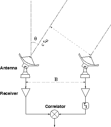
We now consider a more realistic two antenna system (Fig. 7.2), which includes two frequency conversions: e.g. one in the SIS mixer, and one to move the IF band to baseband for numerical sampling and digital correlation. This again is a simplification, but includes all the important effects. The PdB system has in fact 4 frequency conversions (see below).
Let us first consider the effect on phase of a simple frequency conversion.
| (7.2) |
| USB | LSB | |
| frequency: |
|
|
| phase: |
|
|
One antenna is affected by the geometrical delay
![]() , and
by the phase (
, and
by the phase (
![]() in the upper sideband,
in the upper sideband,
![]() in the lower
sideband), which is the quantity to be measured. We apply a
compensating delay
in the lower
sideband), which is the quantity to be measured. We apply a
compensating delay
![]() in the second IF (IF2), as well as a phase
in the second IF (IF2), as well as a phase
![]() to the first LO and a phase
to the first LO and a phase
![]() on the second LO (LO2).
We note
on the second LO (LO2).
We note
![]() the delay
tracking error.
In a 2-antenna system, we may assume that the signal path through the
first antenna suffers no delay of phase offset terms. Obviously the
compensating delay
the delay
tracking error.
In a 2-antenna system, we may assume that the signal path through the
first antenna suffers no delay of phase offset terms. Obviously the
compensating delay
![]() in the second antenna may need to be
negative, if the second antenna is closer to the source: in that
case one will apply the positive delay
in the second antenna may need to be
negative, if the second antenna is closer to the source: in that
case one will apply the positive delay
![]() on the first antenna.
In a
on the first antenna.
In a ![]() antenna system, one will apply phase and delay commands to
all the antennas; a common delay will be applied to all the antennas
since no negative delay can be built with current technology.
antenna system, one will apply phase and delay commands to
all the antennas; a common delay will be applied to all the antennas
since no negative delay can be built with current technology.
Let us first consider the upper sideband of the first LO (second LO conversion is assumed upper sideband for simplicity):
| USB | LSB | |
| HF Frequency (RF) |
|
|
| HF Phase |
|
|
| LO1 Frequency |
|
|
| LO1 Phase |
|
|
| IF1 Frequency |
|
|
| IF1 Phase |
|
|
| LO2 Frequency |
|
|
| LO2 Phase |
|
|
| IF2 Frequency |
|
|
| IF2 Phase |
|
|
| after
|
|
|
| Final |
|
|
|
|
|
|
|
|
|
To stop the fringes in both sidebands we need the following conditions:
| 0 | (7.3) | ||
| 0 | (7.4) | ||
| 0 | (7.5) |
The condition that e.g.
![]() means
that
means
that
![]() must be commanded to vary at a rate
must be commanded to vary at a rate
 |
(7.6) |