

Next: 11.7 Frequently asked questions
Up: 11. Atmospheric Fluctuations
Previous: 11.5 Current phase correction
Contents
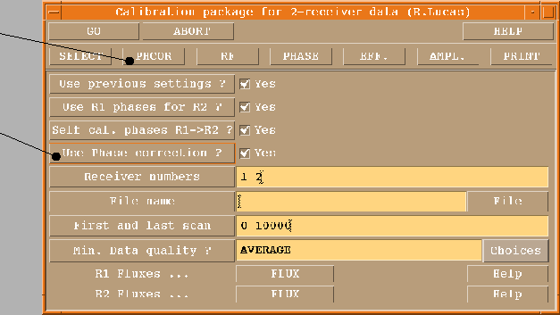
In a typical data reduction session, the atmospheric phase correction hides behind
two unobtrusive buttons (Fig.11.7). The default of the PHCOR
button will calculate the phase correction on a scan basis, i.e. only the corrected
amplitudes will be used and not the phases. There are two reasons to be cautious
about the corrected phases:
- As we have learned from turbulence theory, averages are not good in
describing data which obey a structure function. Adjusting the monitored phases to
zero average can introduce random-like offsets due to slow (large-scale)
components of the atmospheric fluctuations. You can only rely on averages if the
outer scale of turbulence have passed several times over the instrument. This
can be true on your source (typically 20 min integration time), but is doubtful on
the calibrators (integrations of typically 3 min). It may work for compact
configurations depending on wind speed, i.e. it depends on the weather. There may
be an improvement, but it cannot be guaranteed.
- Nearly linear changes in total power can be due to a big water vapor bubble in the
atmosphere or a gain drift in the receivers. The first will produce a phase shift,
the second will not, and the software cannot tell them apart. In most cases, gain
drifts happen when the antenna has just moved a large distance in elevation, as
pump friction and liquid helium distribution change with the receiver cabin tilt.
Such drifts are invisible in the interferometric amplitude (opacity correction),
but the phase correction is more sensitive to them.
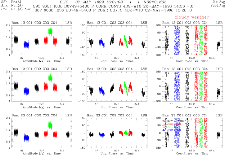
Figure 11.6:
Baseline
based amplitudes, uncorrected phase and monitor corrected phase at 86.2 GHz for a
cloudy data section. The clear sky model over-estimates the correction and would
result in serious amplitude loss. The off-line data reduction software will identify
those parts and disable the correction there.
 |
The part of related header variables is accessible over
CLIC VARIABLES
MONITOR
Some items are scan-based in time resolution, others can be expanded to
a time scale of one second over the total power signal. One can plot the following
quantities related to the phase correction:
- ATM_POWER: total power counts of the monitoring receiver
- ATM_REFERENCE: the offsets which are subtracted from ATM_POWER
- ATM_EMISSION: the calibrated sky emission in Kelvin
- ATM_PHASE: the modeled atmospheric phase
- ATM_UNCORRPH: the astronomical phase uncorrected from
atmosphere
- ATM_CORRPH: the astronomical phase corrected with the model
- ATM_VALIDITY: 0 or 1 whether the phase correction has been declared
valid or not. This flag is antenna specific.
In order to check the validity of the phase correction, the standard reduction runs
the command
CLIC STORE CORRECTION AUTO 15
i.e. CLIC will test
the phase calibrator observations (type P) if the application of the phase
correction improves or degrades the amplitudes, and will declare the correction on
source observations (type O) in a  minutes time window for good.
Apart from AUTO, one can use GOOD and BAD for a manual
override of the diagnostics, and SELF to check the amplitude for each scan
(indifferent to type O or P) for strong sources.
Figure 11.7:
The CLIC calibration
package menu, with phase correction related items marked.
 |


Next: 11.7 Frequently asked questions
Up: 11. Atmospheric Fluctuations
Previous: 11.5 Current phase correction
Contents
Anne Dutrey


![]() VARIABLES
MONITOR
VARIABLES
MONITOR