A telescope, however, is never perfect since mechanical, thermal, and wind-induced
deformations of the structure occur, and the optics may be misaligned and/or have
production imperfections, for one or the other reason. The resulting effect on the
beam pattern is negligible if the corresponding wavefront deformations introduced by
these imperfections are small compared to the wavelength of observation, generally
smaller than
![]() ; the effect is noticeable and disturbing when the
wavefront deformations are large compared to the wavelength (
; the effect is noticeable and disturbing when the
wavefront deformations are large compared to the wavelength (
![]() and
larger). The wavefront deformations due to such imperfections may be of systematic
nature, or of random nature, or both.
and
larger). The wavefront deformations due to such imperfections may be of systematic
nature, or of random nature, or both.
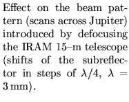
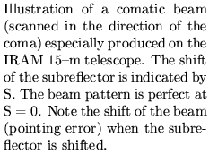
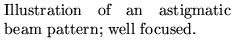
There are three basic systematic surface/wavefront deformations (occasionally associated with pointing errors) with which the observer may be confronted, i.e. defocus, coma, and astigmatism (a transient feature on the IRAM 30-m telescope).
The beam deformation of systematic wavefront deformations occurs close to the main
beam, and the exact analysis should be based on diffraction calculations. A
convenient description of systematic deformations uses Zernike polynomials of order
(n,m) [Born & Wolf 1975]. Without going into details, the Zernike-type surface
deformation
![]() [with (
[with (
![]() ) normalized coordinates of the aperture, and R special
polynomial functions] with amplitude
) normalized coordinates of the aperture, and R special
polynomial functions] with amplitude
![]() has a quasi rms-value
has a quasi rms-value
![]() =
=
![]() and introduces a loss in main beam
intensity of
and introduces a loss in main beam
intensity of
| (1.16) |
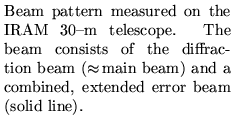
Besides systematic surface/wavefront deformations explained above (mainly due to misalignment of the optics), there are often permanent random deformations on the optic surfaces like ripples, scratches, dents, twists, misaligned panels, etc., with spatial dimensions ranging from several wavelengths to significant areas of the aperture. These deformations introduce identical deformations of the wavefront, which cannot be expressed in mathematical form (as the Zernike polynomials used above). Nevertheless, the effect on the beam pattern of this type of deformations can be analyzed in a statistical way and from a simple expression, the RUZE equation. This equation is often used to estimate the quality of a telescope, in particular as function of wavelength. The values obtained from this equation are directly related to the aperture efficiency, and beam efficiency, of the telescope, and hence are important for radiometric measurements (see Sect.1.5).
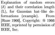
As illustrated in Figure 1.10, there are two parameters which allow a
physical-optics description of the influence of random errors, i.e. the rms-value
(root mean square value) ![]() of the deformations, and their correlation length
L.
of the deformations, and their correlation length
L.
Random errors occur primarily on the main reflector; the other optical components of
the telescope (subreflector, Nasmyth mirror, lenses, polarizers) are relatively
small and can be manufactured with good precision. In order to explain the
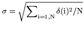
rms-value ![]() , we assume that the reflector aperture is divided into many elements (i = 1,2,...N), and that for each element [i] the deformation
, we assume that the reflector aperture is divided into many elements (i = 1,2,...N), and that for each element [i] the deformation
![]() (i) of the reflector is known with respect to a smooth mean surface. The
rms-value of these random surface deformations is
(i) of the reflector is known with respect to a smooth mean surface. The
rms-value of these random surface deformations is
 |
(1.17) |
| (1.18) |
A description of the wavefront deformation by the rms-value
![]() is incomplete since the value does not contain
information on the structure of the deformations, for instance
whether they consist of many dents at one part of the aperture, or
many scratches at another part. A useful physical-optics
description requires also a knowledge of the correlation length L
of the deformations. L is a number (L
is incomplete since the value does not contain
information on the structure of the deformations, for instance
whether they consist of many dents at one part of the aperture, or
many scratches at another part. A useful physical-optics
description requires also a knowledge of the correlation length L
of the deformations. L is a number (L
![]() ) which
quantifies the extent over which the randomness of the
deformations does not change. For example, the deformations of a
main reflector constructed from many individual panels, which may
be misaligned, often has a random error correlation length typical
of the panel size, but also a correlation length of 1/3 to 1/5 of
the panel size due to inaccuracies in the fabrication of the
individual panels. A typical example is the 30-m telescope
[Greve et al. 1998].
) which
quantifies the extent over which the randomness of the
deformations does not change. For example, the deformations of a
main reflector constructed from many individual panels, which may
be misaligned, often has a random error correlation length typical
of the panel size, but also a correlation length of 1/3 to 1/5 of
the panel size due to inaccuracies in the fabrication of the
individual panels. A typical example is the 30-m telescope
[Greve et al. 1998].
When knowing, by one or the other method, the rms-value
![]() and the
correlation length L, it is possible to express the resulting beam shape in an
analytic form which describes well the real situation. The beam pattern
and the
correlation length L, it is possible to express the resulting beam shape in an
analytic form which describes well the real situation. The beam pattern
![]() ) of a wavefront with random deformations (
) of a wavefront with random deformations (
![]() ,L) [the
telescope may actually have several random error distributions] consists of the
degraded diffraction beam
,L) [the
telescope may actually have several random error distributions] consists of the
degraded diffraction beam
![]() ) and the error beam
) and the error beam
![]() ) such that
) such that
| (1.19) |
| (1.21) |
| (1.22) |
![\resizebox{8cm}{!}{\includegraphics[angle=0.0]{greve7.eps}}](img204.png)
![\resizebox{6cm}{!}{\includegraphics[angle=0.0]{greve8.eps}}](img206.png)
![\resizebox{8cm}{!}{\includegraphics[angle=0.0]{greve9.eps}}](img208.png)
![\resizebox{8cm}{!}{\includegraphics[angle=0.0]{greve10.eps}}](img215.png)
![\resizebox{10cm}{!}{\includegraphics[angle=0.0]{greve11.eps}}](img231.png)