| In order
to drive the Harmonic Mixers at each antenna with a clean and
phase-accurate CW signal, an LO transport system is required.
Historically, the one presented here is the third version. The first
one (up to 1994) used a varactor-tuned VCO which offers fast
tuning and good reliability but has poor phase noise. It has
been
superseded by the LOsystemII ,based on a DRO (dielectric
resonator oscillator) in order to improve the LO phase noise
@1 mm. Actually some units have exhibited very good phase noise
characteristics but all suffered poor reliability from the
mechanically-tuned DRO and
intrinsically slow tuning. The presented version is designed
to
provide low noise, fast tuning and good reliability by means of a
YIG oscillator.
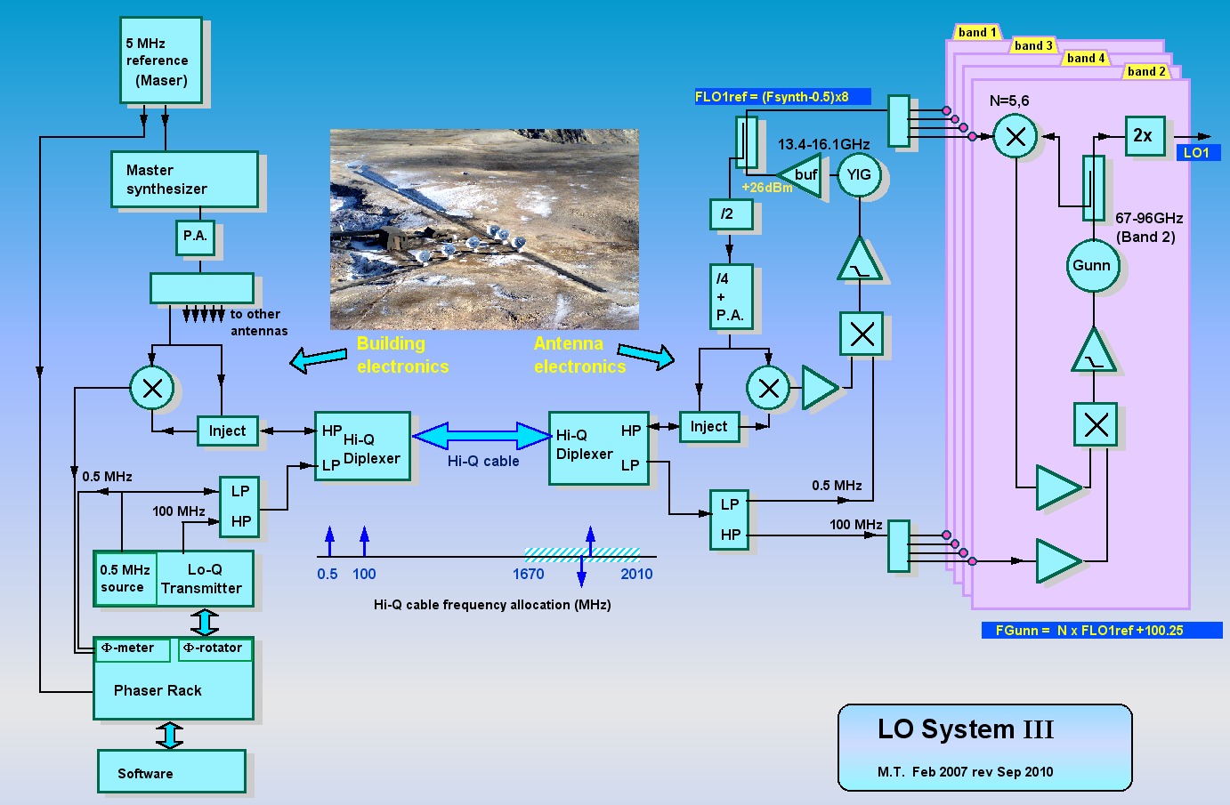
The main change is in feeding the harmonic
mixer in the 15 GHz range. This has been made possible by the availability of
very fast digital frequency dividers. This range has several benefits: - Use much lower harmonic numbers, yielding better S/N for the millimeter phase lock. (typically 7 vs 50) - Global phase noise is significantly improved , mainly due to the YIG performance. - Spurious lines at the HM excitation frequency are now created outside the 4-8 GHz IF. (also true for the future 4-12 GHz) |
| The 0.5
and 100
MHz references are
now transmitted thru the Hi-Q cable. The Lo-Q
cable
network has been disabled. There are two LO1ref modules per antenna, operating at independent frequencies. One serves Band 1 only, the second is shared between Bands 2,3,and 4. No switches or amplifiers are inserted between the LO1ref and the harmonic mixers. Each LO1ref module delivers four copies permanently. The unused outputs must be loaded. When observing in one band, the LO1's of the 3 other bands must be tuned to a defined "parking frequency" in order to avoid contamination of the active receiver. |
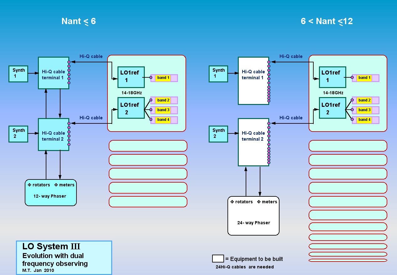
The number of existing Hi-Q cables, and LO1 rotators is currently limited to 12. The diagram above shows how additional antennas can be served. It requires : - Designing new electronics and software for a 24-way Phaser - Building more Hi-Q cable terminals - Pulling a few extra Hi-Q cables to the building More information on phasemeters |