


Next: 7.3 sideband separation
Up: 7. LO System and
Previous: 7.1 An Heterodyne Interferometer
Contents
Subsections
Assume that the conversion loss is negligible for the lower
sideband. At a given IF2 frequency
 the directly
correlated signal is:
the directly
correlated signal is:
 |
(7.7) |
while the sine correlator would give:
 |
(7.8) |
 |
(7.9) |
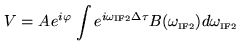
Assume we use a correlator with a finite bandwidth
 . The
correlator output is obtained by summing on frequency in the IF
passband:
. The
correlator output is obtained by summing on frequency in the IF
passband:
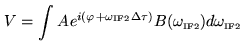 |
(7.10) |
where
 is a complex passband function
characteristic of the system: gain of the amplifiers and relative
phase factors.
is a complex passband function
characteristic of the system: gain of the amplifiers and relative
phase factors.
 |
(7.11) |
We have assumed that the source visibility is constant across the
band; the source visibility, when the delay error varies, is
multiplied by the Fourier transform of the complex passband.
The delay error must be kept much smaller than the inverse of the
instantaneous bandwidth to limit the signal loss to a small level.
The delays are usually tracked in steps, multiples of a minimum
value. To limit the loss to 1%, the minimum delay step must be
 (0.5 ns for a 500 MHz bandwidth).
In that case the signals coming from the upper and lower sidebands
have similar attenuation in the RF part and similar conversion loss
in the mixers. They will have similar amplitudes in the correlator
output. The result for the cosine correlator is:
Assuming the same visibility in both sidebands:
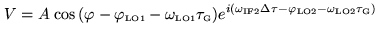 |
(7.13) |
If the delays are tracked, and the LO phases rotated as above, the
exponential term is 1 and only the real part of the visibility is
measured. Some trick is thus needed to separate the signal from the
sidebands.
Next: 7.3 sideband separation
Up: 7. LO System and
Previous: 7.1 An Heterodyne Interferometer
Contents
Anne Dutrey