 |
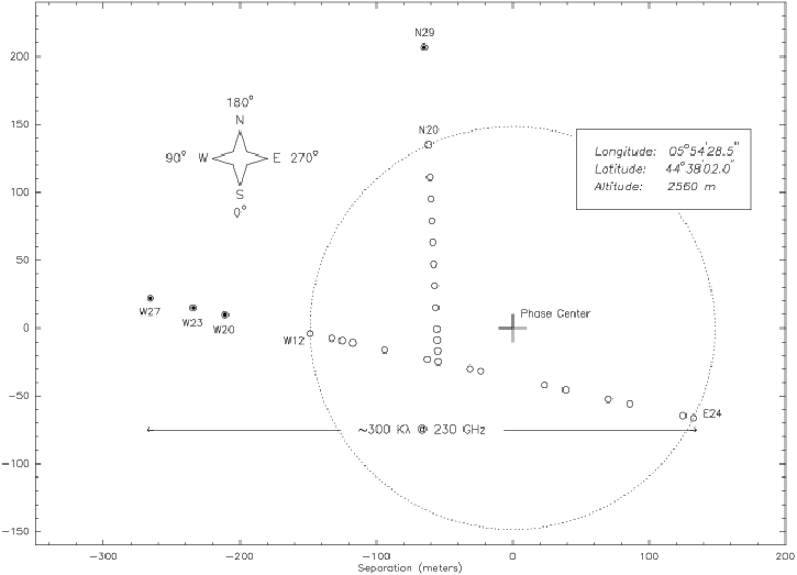
Currently, the interferometer consists of five antennas arranged in a T-shaped pattern extending over a maximum of 408 meters east-west and 232 meters north-south. A sixth antenna is expected to be ready for 2002, and the extension of the northern track is still under construction.
The antennas are conceptually identical: they all have a fully
steerable alt-az mount which incorporates a self-propelled
transporter for moving the antennas (130 tons) along the tracks
between stations. Each antenna is a 15m diameter Cassegrain
telescope with the backstructure and quadrupod legs largely made
of carbon fiber for high thermal stability. The high precision of
the reflecting antenna surface (40-60![]() m) guarantees best
performance: all antennas have essentially the same sensitivity
(22Jy.K
m) guarantees best
performance: all antennas have essentially the same sensitivity
(22Jy.K![]() at 3mm, 35Jy.K
at 3mm, 35Jy.K![]() at 1mm - see
Chapter 12 by A.Dutrey), and very similar pointing and
focussing characteristics.
at 1mm - see
Chapter 12 by A.Dutrey), and very similar pointing and
focussing characteristics.
All the antennas are equipped with dual-frequency SIS receivers operating simultaneously
in the 82GHz![]() 115GHz and 205GHz
115GHz and 205GHz![]() 245GHz range. Typical double sideband receiver
noise temperatures are between 25K and 50K at 3mm and between 40K and 60K at
1mm. The receivers upper and lower sidebands are separated by the correlators with a
rejection better than 26dB. The lower to upper sideband gain ratio depends on the
receiver and varies typically between 0.2 and 4.0 under standard operating conditions in
the 3mm band, and yields essentially a double-side band tuning in the 1mm band. Pure
single sideband tuning (with rejection 15 to 25 dB) is also possible in the 3mm band,
with receiver temperatures around 60 to 80K.
245GHz range. Typical double sideband receiver
noise temperatures are between 25K and 50K at 3mm and between 40K and 60K at
1mm. The receivers upper and lower sidebands are separated by the correlators with a
rejection better than 26dB. The lower to upper sideband gain ratio depends on the
receiver and varies typically between 0.2 and 4.0 under standard operating conditions in
the 3mm band, and yields essentially a double-side band tuning in the 1mm band. Pure
single sideband tuning (with rejection 15 to 25 dB) is also possible in the 3mm band,
with receiver temperatures around 60 to 80K.
Eight totally independent correlators units are available that
provide an 87% correlation efficiency (for more details see
Chapter 6by H.Wiesemeyer). Each correlator unit
provides by default 7 choices of bandwidth/channel configurations
down to a nominal velocity resolution of 50m.s![]() at
230GHz. The correlators can independently be connected either to
the 3mm or to the 1mm receiver (100-650 MHz) IF2.
at
230GHz. The correlators can independently be connected either to
the 3mm or to the 1mm receiver (100-650 MHz) IF2.
A central control computer coordinates the entire interferometer (antennas, receivers and correlators and quite some other equipment) and makes the data acquisition. Raw data corresponding to the individual dumps of the correlator buffers will not be available as real-time jobs apply automatic calibrations (clipping correction, apodization, FFT, sideband separation, small delay correction, bandpass correction and other corrections) and make automatic data quality assessments (marking bad data, shadowing, phase lock, just to cite a few flags) before data is written to disk. A second workstation provides the software resources for offline data analysis and for data archiving before transfer to the Grenoble headquarters.