 |
In many cases the correlator can be split in several independent sub-bands that are centered to different IF frequencies, and thus observe different frequencies in the sky. In principle they can be treated as different receivers since they have different anti-aliasing filters and different delay offsets, due to different lengths of the connecting cables. Thus they need independent bandpass calibrations, which can be done simultaneously on the same strong source.
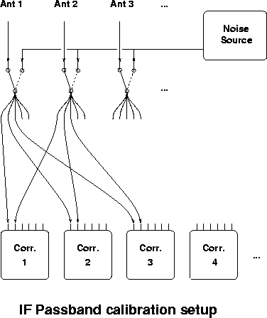
At millimeter wavelengths strong sources are scarce, and it is more practical to get a relative calibration of the sub-bands by switching the whole IF inputs to a noise source common to all antennas (Fig. 7.1). The switches are inserted before the IFs are split between sub-bands so that the delay offsets of the sub bands are also calibrated out. This has several advantages: the signal to noise ratio observed by observing the noise source is higher than for an astronomical source since it provides fully correlated signals to the correlator; then such a calibration can be done quite often to suppress any gain drift due to thermal variations in the analogue part of the correlator. Since the sensitivity is high, this calibration is done by baseline, so that any closure errors are taken out.
When such an ``IF passband calibration'' has been applied in real time, only frequency dependent effects occurring in the signal path before the point where the noise source signal is inserted remain to be calibrated. Since at this point the signal is not yet split between sub-bands, the same passband functions are applicable to all correlator sub-bands.
At Plateau de Bure an ``IF passband calibration'' is
implemented. Of course when the noise source is observed the delay and
phase tracking in the last local oscillators (the one in the
correlator IF part) are not applied.