next up previous contents
Next: 7.2.4 Side band calibration Up: 7.2 Bandpass calibration Previous: 7.2.2 IF passband calibration

Subsections

7.2.3 RF bandpass calibration

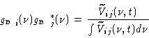
To actually determine the functions $\mbox{\ensuremath{g_\mathrm{\scriptscriptstyle B}} }_i(\nu)$ we observe a strong source, with a frequency-independent visibility. The visibilities are

\begin{displaymath}\ensuremath{\widetilde{V}} _{ij}(\nu,t) = \mbox{\ensuremath{g...
...mathrm{\scriptscriptstyle C}} }_i^*(t) \ensuremath{V} _{ij}(t)
\end{displaymath} (7.14)

Then

\begin{displaymath}\mbox{\ensuremath{g_\mathrm{\scriptscriptstyle B}} }_i(\nu) \...
...j}(\nu,t)}{\int{\ensuremath{\widetilde{V}} _{ij}(\nu,t) d\nu}}
\end{displaymath} (7.15)

since the frequency independent factors cancel out in the right-end side. One then averages the measurements on a time long enough to get a decent signal-to-noise ratio. One solves for the antenna-based coefficients in both amplitude and phase; then polynomial amplitude and phase passband curves are fitted to the data.

7.2.3.0.1 Applying the passband calibration

The passband calibrated visibility data will then be:

\begin{displaymath}\mbox{\ensuremath{\widetilde{V}_\mathrm{\scriptscriptstyle C}...
...)\mbox{\ensuremath{g_\mathrm{\scriptscriptstyle B}} }_j^*(\nu)
\end{displaymath} (7.16)

the amplitude and phase of which should be flat functions of frequency.

7.2.3.0.2 Accuracy

The most important here is the phase precision: it sets the uncertainty for relative positions of spectral features in the map. A rule of thumb is:

\begin{displaymath}\Delta \theta /\theta_{B}= \Delta \phi /360
\end{displaymath} (7.17)

where $\theta_{B}$ is the synthesized beam, and $\Delta \theta$ the relative position uncertainty. The signal to noise ratio on the bandpass calibration should be better than the signal to noise ration of the spectral features observed; otherwise the relative positional accuracy will be limited by the accuracy of the passband calibration.

The amplitude accuracy can be very important too, for instance when one wants to measure a weak line in front of a strong continuum, in particular for a broad line. In that case one needs to measure the passband with an amplitude accuracy better than that is needed on source to get desired signal to noise ratio. Example: we want to measure a line which is $10\%$ of the continuum, with a SNR of 20 on the line strength; then the SNR on the continuum source should be 200, and the SNR on the passband calibration should be at least as good.


next up previous contents
Next: 7.2.4 Side band calibration Up: 7.2 Bandpass calibration Previous: 7.2.2 IF passband calibration
S.Guilloteau
2000-01-19