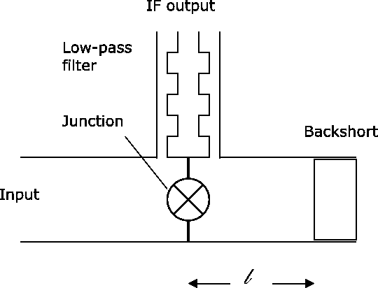
One end of the waveguide is the input of the mixer; the other end must be
terminated somehow. At the zero-order approximation, one would like the
junction to ``see'' an open circuit when ``looking into'' the rear end of
the waveguide. More generally, the junction should see a pure imaginary
impedance, so that no energy is wasted. A simple calculation shows that a
transmission line having a length ![]() , and terminated into a
short-circuit, has an apparent impedance:
, and terminated into a
short-circuit, has an apparent impedance:
For various reasons (one of which is reducing the noise
contribution from the atmosphere) it is desirable that the mixer
should operate in single-sideband mode. We explain how this
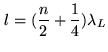
is achieved with a crude zero-order model. Assume that the best
impedance match of the junction is obtained when the apparent
impedance of the backshort seen from the junction is an open
circuit. Assume we observe in the lower sideband at a frequency
![]() , and want to reject the upper sideband
, and want to reject the upper sideband
![]() . That condition can be achieved if, at
the frequency
. That condition can be achieved if, at
the frequency ![]() , the junction is short-circuited. So, we
must meet the two conditions:
, the junction is short-circuited. So, we
must meet the two conditions:
 lower sideband lower sideband |
|||
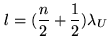 upper sideband upper sideband |
Returning to practicalities, tuning a receiver requires several steps
(which used to make astronomers a bit nervous at the 30-m telescope when
all was done manually). First the local oscillator must be tuned and
locked at the desired frequency. Then the backshort is set at the
appropriate position, and the junction DC bias voltage is set. Finally the
LO power is adjusted to reach a prescribed junction DC current (of the
order of ![]() ). These adjustments are made by a combination of table
lookup and optimization algorithms under computer control. Altogether this
involves between 11 and 13 adjustments, mechanical or electrical, yet
this process takes only a few minutes with the current systems.
). These adjustments are made by a combination of table
lookup and optimization algorithms under computer control. Altogether this
involves between 11 and 13 adjustments, mechanical or electrical, yet
this process takes only a few minutes with the current systems.