Terms of use | Contact us
Copyright © 2009-2023 IRAM. All rights reserved.
YOU ARE ON THE LEGACY WEBSITE OF IRAM. YOU WILL FIND THE CURRENT WEBSITE HERE.
The Band 7 Cartridge (275-373 GHz) for ALMA
From 2002 to 2007, IRAM has been involved in the design, integration and test of ALMA Band 7 pre-production cartridges (receiver systems for the ALMA antennas), covering the signal frequency range 275-373 GHz.
 Following the successful Preliminary Acceptance In-house of eight receivers, and after some negotiations, a contract was signed on December 3rd, 2007 between IRAM and ESO to produce 48 ALMA Band 7 receivers over the next 4 to 5 years with an option for 17 extra receivers for Japanese antennas that was signed in the summer 2008.
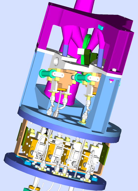
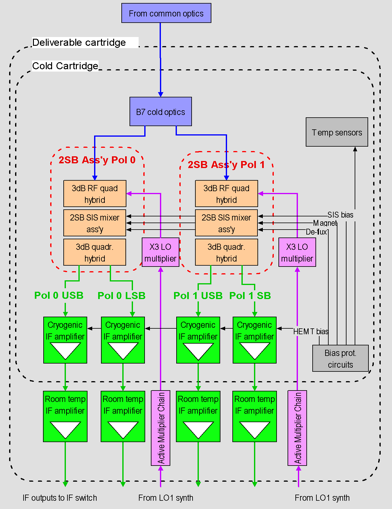
The cartridge had to meet a number of specifications, including SSB noise temperature less than 147K, but also –10dB image band suppression, total power stability, 7.1 fs2 long term phase stability, beam pattern, etc… The front end for ALMA consists of a 4-K cryostat with ten insertable receivers called cartridges covering the frequency range 31 to 950 GHz. Each cartridge will operate simultaneously in two linear polarizations. A block diagram of the Band 7 cartridge and an overall view of the #1 cartridge is given below. The cartridge consists in three cold stages with operating temperatures of 4K, 20K and 90K and a room temperature baseplate which is the interface between the vacuum and the air. The stages are supported by G10 glass fiber tube spacers. The four plates and GFRP tubes constitute the blank cartridge, designed and supplied within the ALMA project by Rutherford Appleton Laboratories (UK).
The 4 K assembly comprises:
- The cold optics, consisting of three off-axis elliptical mirrors and a polarization diplexing grid, designed to achieve near-optimum coupling of the cartridge to the telescope within prescribed tolerances;
- The two dual-sideband (2SB) mixer assemblies;
- A thermal sink for the four HEMT amplifiers, physically mounted on the 20K stage but isolated from it, and thermalized to the 4K stage for improved stability and better noise performance;
- Mechanical structures to support these elements in the adequate positions within tolerances.
The 20K stage only provides thermal shunts for wiring, IF coaxial cables, amd LO waveguides, as well as mechanical (thermally insulated) support for the HEMT amplifiers. The 90K stage has the two LO triplers, wiring thermal shunts mounted on it. The 300K baseplate supports the ESD protection board and the IF, DC and LO feedthroughs.
 |
 |
|
Band 7 cartridge block diagram |
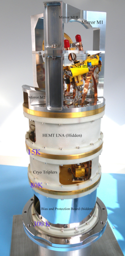
Complete Band 7 Cartridge |