


Next: 14. Plane Analysis
Up: 13. Calibration of data
Previous: 13.2 The ``First Look''
Contents
Subsections
We describe here, step by step the inputs and actions (or outputs) of the procedure
``Standard Calibration (2 receivers) ''. The associated panel is given in
Fig.13.2.
Figure 13.2:
``Standard Calibration (2 receivers)'' panel
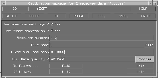 |
On the panel, the reducer should select with the mouse the ``File name'' of the header file. Other parameters are
automatically selected by the procedure if the flag ``Use
previous settings'' is set to YES which is the default.
Never change it if your data are correct (no editing). The
parameters ``First and last scan'' are selected
automatically when ``Use previous settings'' is set to YES. The default value for the flag Min.Data quality is
AVERAGE. The flag ``Use Phase correction'' must also
be set to the default: YES. The current procedure uses by
default the phase calibration of the receiver 1 to calibrate the
instrumental phase of the receiver 2 because the experience has
shown that it is the most efficient way to proceed (see R.Lucas
lecture on phase calibration). Therefore, the calibration of the
receiver 2 (1.3mm) cannot be dissociated from the calibration of
the receiver 1 (3mm) and the flag ``Receivers numbers''
must be set to 1 2, except when observations were done at
3mm only.
Finally, the inputs ``R1 Fluxes'' and ``R2 fluxes'' are associated
(when needed) to the action EFF)
To calibrate your data, you need to do the following actions leading to the output
calibration, in order:
- SELECT: Select the calibration parameters
- PHCOR: Radiometric phase correction, equivalent to a
``Monitor 0'', see A.Dutrey lecture.
- RF: Radio Frequency calibration
- PHASE: Instrumental phase calibration versus time
- EFF: Efficiency (Jy/K) calibration, to determine the
flux densities of the amplitude calibrator. The inputs ``R1 Fluxes'' and ``R2 Fluxes'' should be used here.
- AMP: Amplitude calibration versus time
- PRINT: To produce the LaTeX and PostScript files
containing the calibration curves (e.g.
28-feb-2001-x007.ps).
By typing GO, all the actions listed above are done sequentially. The reducer
has just to type continue under CLIC (or use the ``Continue'' button in the
top left menu) at each step of the calibration process.
After a few general comments about quality of the data, including the measurement of
the seeing (deduced from the rms of the fit of the temporal phase), the pages 1 and
2 summarize the calibration as follows:
- §1.1 The estimated flux densities of the calibrators at the
observed frequencies.
- §1.2 The efficiencies of the antennas for receivers 1 and 2
(which are deduced by fixing the flux of one or several calibrators).
- §1.3 The hour angle observed on the source
- §1.4 The table of the rms obtained on the RF calibration for receivers
1 and 2 in both upper and lower sidebands
- §1.5 The table of the rms obtained the temporal fit for the phase and the
amplitude per baselines. Note that for receiver 2, the rms given in Col.1 is exactly
the product of frequency ratio (rece 2/rece 1) times the rms obtained on receiver 1
because the phase on the receiver 1 is used to calibrate the phase on the receiver
2. After applying this phase correction, a second fit is performed on the residuals,
its rms is displayed on Col.2. Col.3 gives the rms obtained on the amplitude (in
%).
Next: 14. Plane Analysis
Up: 13. Calibration of data
Previous: 13.2 The ``First Look''
Contents
Anne Dutrey